U20 Solex Engine (2 Feb 2009)
I picked up this Solex U20 w/5 speed from Florida. I had previously bought a U20 (also in Fl...block on engine stand) and disassembled to "learn" about the engine. I grew up on 510s and the L series overhead, but the U20s two chain system with jackshaft was a whole new world to understand. The second FL engine ran, but had serious leaks and compression problems.
Solex U20 running (2 Feb 2009)
The link above is the Solex U20 running as I purchased it. It needed starting fluid to kick it over and ran very rough. After running I discovered a severe leak in the pass rear side of the head (turned out to be a broke head bolt that allowed water to leak across to the main oil passage). The engine also had low compression 120/110/110/105 from 1 to 4. The headers were rusted thru and the Solex's were rough to say the least.
.jpg)
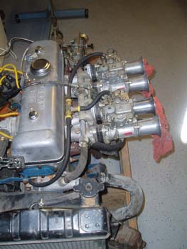
Mikuni Solex 44 PHH Carbs (3 Feb 2009)
These are the Solex carbs that came as an option on the 2000 Roadsters. The upgrade kit came with the carbs,a 'B' Cam (higher lift/duration), and a larger sump oil pan. The 67.5 2000 also had the 8000 RPM Tach and a 160 Speedo to go with the performance upgrade. These are actually later style carbs as early carbs had two screws on the jet block (I had a set, but sold them as many have said the new style were easier to tune/adjust).
Bad Leak (3 Feb 2009)
After getting the engine to run using a Gary Boone EI dizzy (now available thru our vendors or directly at East Coast Roadsters), I quickly noticed a large leak in the back corner (as seen in the photo). I also had low compression in all four cyl, but the lowest was of course that back cyl (#4).
.jpg)
.jpg)
Teardown of U20 (20 Feb 2009)
I had to tear down the engine I purchased due to a leak in the rear corner...the leak started from a broken head bolt. The engine was very corroded and the compression was very low.
Timing Chains (20 Feb 2009)
If you're lucky enough to buy new Nissan chains they will have "bright" links to help align them with their gears..if not you will need to link count and mark your replacement chains.
.jpg)
.jpg)
Chains removed (20 Feb 2009)
The top arrow is the oil restrictor found behind the lower chain tensioner, the small arrow is the main oil gallery plug...these plugs should be removed to clean the main oil gallery.
Main Bearing Caps (20 Feb 2009)
Prior to removing the woodruff keys off the crank nose count the shims that are in place...these are used to properly install the damper for fore/aft alignment.
.jpg)
.jpg)
Block Tanked (15 Nov 2010)
Back from another deployment and picking up where I left off! After removing the crank and the jackshaft I took the block to a machine shop that still 'hot tanks' blocks...due to strict environmental rules many have moved to blasting verses using chemical tanks. If you do tank the block the jackshaft bearings will be ruined in the cleaning process (replacements are available from our vendors).
Oil passages (15 Nov 2010)
The top arrow is the main oil gallery...there is a plug on the front and back of the block. These are metal 'slugs' and should be removed to ensure this critical passage is clear of sludge and debris. The lower arrow is the lower tensioner oil passage...there is a restrictor installed at this location. I had the machine shop tap my main oil gallery for threaded plugs.
.jpg)
.jpg)
These are the oil gallery plugs I mentioned in the previous photo. They measure just over a half inch. Notice the original has a hole as I drilled one thru and used a long rod to knock the opposite end out...I simply flipped the block and knocked out the drilled slug. My neighbor (gunsmith) who owns his own lathe quickly turned two new plugs, but I actually went with the two threaded plugs after having the block tapped.
Final cleaning (16 Nov 2010)
My final step before assembly was to do one more cleaning of all passages to remove any dirt or residue left from the machine shop work. A few brushes and some light soap...avoid chemicals that could ruin the already installed bearings.
.jpg)
.jpg)
Ready for paint (17 Nov 2010)
After drying the block completely I put tape over all threads and passages and did a final wipe with Marine Clean to remove any oils and contaminants from my tape job.
Soft Plug Install (18 Nov 2010)
I painted the block red (not the correct Datsun color...see vendors for the correct blue/green block paint). I chose red because it's what I wanted...my car will be a 67.5 2000 clone, so it's already "wrong", but I hope the red will look good against the black engine bay. I installed the freeze plugs after I painted...use a large socket and tap the plugs in square and flush to the block.
.jpg)
.jpg)
Block Ready (21 Nov 2010)
After putting a final coat on the block I gave it a few days to cure...unfortunately my water passages are starting to flash rust and I don't want to spray any other chemicals into the block...I guess I will be doing a radiator flush after I run it on the test stand.
Jackshaft Bearing (21 Nov 2010)
This is a quick shot of the middle jackshaft bearing. The bearings are available as one piece or 'split bearings' from our vendors. The front and middle have one hole that will match up with the oil passage. The rear bearing MUST have three holes match up...see next photo.
.jpg)
.jpg)
Last Blast for the Passages (21 Nov 2010)
Today I start putting components back in the block...prior to starting I gave all the passages one more quick cleaning. This also has a clear view of how the jackshaft bearings align with the holes in the block.
Rear Jackshaft Bearing (21 Nov 2010)
The rear jackshaft bearing MUST have all three holes (pipe cleaners) in the bearing lined up in the block, the top hole is the only passage that allows oil to get up to the valve train thru a channel on the jackshaft. Notice there is a rear brass freeze plug, and a large plug fills the gap between the rear bearing and the back of the block. (the plug on the left is the new threaded main oil gallery plug).
.jpg)
.jpg)
Rear Main Seal (22 Nov 2010)
The Roadsters rear main seal is a two piece 'rope' seal. The pieces come with plenty of extra length. The seal goes in the outside slot...you can use a large socket to press it into place or the crank itself can be used to press the seal in.
Rear Main Seal Cut (22 Nov 2010)
After the seal is seated you must trim the excess...this step can be the difference between a good sealed rear main or an oil leak. The pieces need to be cut close to the block yet a small amount should be above the block about 1/8 of an inch (see photo). Not too short or too long. As Scott Sheeler says in his Roadster book "Like Baby Bear said, 'Just Right'!"
.jpg)
.jpg)
Main Bearings (22 Nov 2010)
I pre lubed all main bearings and installed the crankshaft.
Rear Cap Seals (22 Nov 2010)
After loosely installing the crank give it a few taps on both ends to center the thrust bearing and then torque to a final 65ft lbs in three increments. After the caps are tight you must install the side rear main seals. Simply rub some oil on them and slide them (lightly tap) into their slots (they should install flush). Give the crank a few turns to ensure all is well (I used some old flywheel bolts offset and a breaker bar)
.jpg)
.jpg)
Oil Restrictor (23 Nov 2010)
Before I continue today I installed the small threaded oil restrictor for the lower chain tensioner...it's a small hole, but the restrictor is even smaller...don't forget this piece!
Rod Bearings (23 Nov 2010)
My old bearings were pretty worn (bottom), the top bearing is the replacement. The bearings have tabs which clearly match the same tabs in the rods.
.jpg)
.jpg)
Piston Rings (23 Nov 2010)
I installed all of the rings on the four pistons.
Pistons Ready (23 Nov 2010)
After all rings were installed I prepared for the pistons installations. The rods/pistons have a forward facing side (there is an 'f' by the oil hole). My rods and caps are also numbered, so I layed everything out as it would be installed.
.jpg)
.jpg)
Ring Gap Offset (23 Nov 2010)
Before compressing the rings I offset the rings 180 degrees out from the previous ring.
Rod Bolts (23 Nov 2010)
Before installing the pistons I covered all of the rod bolts to avoid contacting/scratching the crank journals.
.jpg)
.jpg)
Piston In! (23 Nov 2010)
Installing the first piston...I simply rotated the crank to put that journal at the bottom of its stroke. I slid the piston down, removed my rod bolt protectors, pulled the piston into place, pre-lubed the bearing, and installed the cap. Next I torqued in three steps to 20, 40, and final to 65ft lbs.
Final Piston (23 Nov 2010)
#4 going in...notice 2 & 3 are at the top of their stroke while #1 and of course #4 are at their bottom.
.jpg)
.jpg)
Pushing Piston In (23 Nov 2010)
After getting the pistons past their rings you need to push the piston down to it's crank journal. Normally you can oil the rings and they will slide easier, but I used new chrome rings and they need to 'seat' before they are oiled.
Jackshaft In (29 Nov 2010)
Moving on, I flipped the block over and installed the jackshaft. I simply lubed the jackshaft bearings and a coat on the jackshaft journals and carefully slid it in...the only caution is not installing it too far back as the rear only has a cap...it's the locating plate at the front that holds it in place.
.jpg)
.jpg)
Jackshaft Plate (29 Nov 2010)
Well the jackshaft locating plate was not hard to put on, but as you can see from previous photo I had installed the keys in the keyway and the locating plate wouldn't slide over, so I knocked them out and installed the plate, then reinstalled the keys. I also bought a new tool as I've never owned a screwdriver that was a torque wrench, but low and behold they have them...torque the two screws to 4 ft lbs.
The "Evil L" (29 Nov 2010)
Probably the most famous engine component of the U20 is the Evil L. It's actually the upper chain guide and the top has a small bracket (L from a side view) designed to hold the cam chain sprocket in place while the head is removed...problem is the chain tensioner is driven by oil pressure, so if the chain has slack or the timing components are worn the chain rubs on the Evil L (very noticeable at start up). One solution is to cut the evil l off or best solution...fix the cause of the slack chain.
.jpg)
.jpg)
My Evil L (29 Nov 2010)
My solution was discussed on one of the Roadster forums. I took my new Upper chain guide purchased for the rebuild and pieces I cut off of the old chain guide (which was worn and no good anyway) and made mine removable.
Rear Jackshaft Gear (29 Nov 2010)
Moving along...I installed the lower chain guide (many leave this off, but I paid for a new one, so on it goes!), then I put the upper chain on the Cam sprocket and the rear jackshaft sprocket. I purchased new chains, but they were not Nissan chains so I had to mark two links with paint by counting 38 chain links between them. Simply align the shiny (marked) links with the dimples in the sprockets. The Cam sprocket should install at approx 3 O'clock and the lower sprocket will be at 5 O'clock as seen in photo.
.jpg)
.jpg)
3 O'Clock (29 Nov 2010)
This is the Cam sprocket at the 3 O'clock as discussed in the previos photo...in these two positions the upper chain is is it's "assembly" position.
Lower Chain (29 Nov 2010)
Same problem with my new lower chain (no shiny links)...so I counted 16 1/2 links and painted dots. I can't even describe all of the steps to this (buy Scott's book and you can't fail), but after installing the sprockets you can check them by aligning the two timing dimples and the rear jackshaft sprocket will be back at 5 O'clock...all of the marks should form a straight line.
.jpg)
.jpg)
Chains complete (29 Nov 2010)
I've checked and rechecked and the chains seem to be aligned correctly, all marks line up at TDC and in the 'Checking' position.
Lower Chain Tensioner (29 Nov 2010)
I installed a new lower tensioner...a Roadster member (see Gordon's Garage) described an easy way to install the tensioners...simply zip tie them in the compressed position, install, and then cut the zip tie.
.jpg)
.jpg)
Chains Marked (2 Dec 2010)
The chains have two check positions...the aligned marks in a previous photo and this position. To get this step correct I had to mark two links as the sprocket mark must land between two links.
Oil Slinger (2 Dec 2010)
The next step is to install the oil slinger. The Slinger fits with the raise section forward.
.jpg)
.jpg)
Top Dead Center (2 Dec 2010)
The final check before putting the front cover on is to verify TDC...the more precise you are with installing the chains and finding TDC, the better off the rest of the install will be.
Front Cover (2 Dec 2010)
I installed a new front seal in the front cover and fit it to the front of the block.
.jpg)
.jpg)
Water Pump (2 Dec 2010)
Next I bolted up the water pump, although not necessary, I placed sealer around the front cover water passage and used anti seize on all of the water pump bolts.
Crank Damper (2 Dec 2010)
With the front cover installed I torqued the crank damper on to 145 ft lbs. I held the crank in place with offset flywhel bolts on the opposite end. The pulley has 5 marks from 0 degrees to 20 with 5 degree increments. At TDC the pulley lined up perfect to the largest mark (O degrees).
.jpg)
.jpg)
Rebuilding the Oil Pump (3 Dec 2010)
I completely disassembled the oil pump and checked the gears...this also provides an easy access to ensure the screen is completely shaped.
Ready for Install (3 Dec 2010)
I prelubed the internals and gave it a few quick spins...the pump is ready to be installed.
.jpg)
.jpg)
Oil Pump In (3 Dec 2010)
With the block upside down, place the oil pump gasket on and slide the pump into position. I also installed a new oil pan gasket...I chose not to use the factory cork gasket and went instead with a thick reusable rubber one offered by Dean.
11:25 Drive Gear (3 Dec 2010)
This is another difficult U20 piece...after installing the oil pump you need to install the Dizzy drive gear. It should end as above (11:25 with the small lob forward). This step is critical to correct engine timing. If you set everything right during the chain install, the gear will drop into this position without problems.
.jpg)
.jpg)
Dizzy Support (3 Dec 2010)
To keep the drive gear in I installed the dizzy tower and while working that side of the block I installed all passenger side items.
Combustion Chamber (4 Dec 2010)
Since I rebuilt the bottom end, I really wanted to spend some time on the head. This is the combustion chamber on the U20 head all cleaned up.
.jpg)
.jpg)
Valve Guides (4 Dec 2010)
I purchased new valves and seats and had a machine shop do the initial cuts.
Valve Lapping (4 Dec 2010)
I lapped each valve prior to their final install.
.jpg)
.jpg)
Valve Lapped (4 Dec 2010)
After lapping the valve, the valve and seat get a dull finish where the compound makes the final "cut".
Intake Port (4 Dec 2010)
This is holding the gasket up to the head, this gasket came in a kit...it was really large and I wasn't going to open the port any more than I did, the good news the gasket that Dean sells with his headers was just right!
.jpg)
.jpg)
Valve Springs (5 Dec 2010)
After all of the valves were complete I installed the valve springs. I went with a comp spring. I purchased a press to do the brake rotors and it came in very handy to install the Nissan springs.
Solex Cam In! (5 Dec 2010)
After all of the springs were complete, I installed the Cam. The Solex cam has a higher lift/longer duration than the U20 standard cam. I simply put assembly lube on the cam towers and then torqued the caps. The cam should turn freely at this point. Since there are no rockers I simply set the cam to TDC (front lobs both up) and transferred the cam sprocket from the Evil L bracket.
.jpg)
.jpg)
Upper Chain Tensioner (5 Dec 2010)
Using the old zip tie trick, I lowered the upper chain tensioner into place.
Shimmed! (5 Dec 2010)
To ensure my chain always has tension I shimmed the tensioner so it can't compress back in...this is a new setup so there really isn't a lot of slack to take up. I used two washers which were ground flat at the back to ride evenly with the tensioners 'shoe'.
.jpg)
.jpg)
Rockers In! (5 Dec 2010)
I installed all rockers and their adjustment/jam nuts. I rough set them as they will will need a HOT clearance of Intake Valves = .0079 in and Exhaust valves =.0118 in.
Almost Done (6 Dec 2010)
Picking up where I left off. I test fit the manifolds yesterday, but decided I would move the engine as is on to a test stand and then bolt the additional parts on.
.jpg)
.jpg)
Last Items (6 Dec 2010)
Finishing up last items...I put anti sieze on the thermo housing bolts (these seem to be a problem area in older engines).
Thermo Gaskets (6 Dec 2010)
Use the correct gaskets for the thermostat...the two gaskets have a small metal staple that allows the thermo cover to ground so the temp gauge works correctly.
.jpg)
.jpg)
Ready for Transfer (6 Dec 2010)
All set...I installed my GB Dizzy (the engine was at TDC so I simply aligned the rotor per his easy to follow direction. I have had this Dizzy for awhile...been collecting for years). These EI Dizzy's are still available at East Coast Roadsters.
Roadster 5 Speed (7 Dec 2010)
This is the 5 speed that will go on this motor...I have new bearings and gaskets for it so it is due a workover. I will use a temp transmission and this one will go on when the engine is moved to the frame.
.jpg)
.jpg)
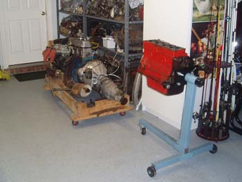
On Stand! (7 Dec 2010)
Ok, with the temp transmission attached I installed the engine on my test stand. Although I have a full comp flywheel (11.5 lbs), I chose to go with a modified one for this engine (17 lbs) vs. the stock one at 22.5 lbs. That is the nice thick manifold gasket that Dean offers.
Solex intake (7 Dec 2010)
I installed new ceramic coated headers from DatsunParts.com as well as a new gear reduction starter. Although not needed, the gear reduction starter is shorter than the standard starter (and looks darn good too). See Solex page for carb rebuild.
.jpg)
.jpg)
Ready to Run (4 Jan 2011)
After rebuilding the Solex carbs, I installed a temporary radiator/transmission/alternator/and a manual fuel pump...with some quick adjustments it started right up...now on to jetting the Solex's correctly.